Assembly Instructions
Overview
This section describes the step-by-step mechanical assembly of the quadruped’s leg modules. Each step includes annotated diagrams and warnings where necessary. Ensure that all servo horns have been centered before beginning assembly.
Warning
⚠️ Always verify that each servo is mechanically centered before mounting. Misaligned horns will cause uneven torque and offset errors during calibration.
1.0 Assemble the Trochanter
The trochanter unit connects the main frame to the proximal leg servos. Make sure that the servo horns are attached only after electronic centering.
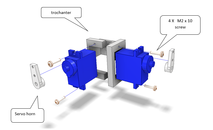
Fig. 15 Figure 1 – Assembly of the trochanter segment.
Parts required:
2 × Servo (standard 180°)
1 × Trochanter frame bracket
2 × Servo horns
4 × M2 × 10 mm screws
Assembly steps:
Mount both servos into the trochanter frame.
Fasten using 4 × M2×10 mm screws as shown in the figure.
Attach the servo horns once the servos are centered electronically.
Note
The trochanter acts as a pivot segment and should rotate freely after assembly. Do not overtighten the servo screws — this may deform the plastic housing.
2.0 Mounting the Coxa
The coxa connects the trochanter to the femur segment. Align the servo output shaft perpendicular to the trochanter bracket.
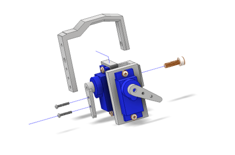
Fig. 16 Figure 2 – Mounting the coxa segment.
Steps:
Insert the servo horn into the coxa bracket.
Secure with M2 screws and washers.
Verify that the coxa rotates smoothly through its full range.
3.0 Attaching the Femur
Once the coxa is in place, attach the femur linkage.
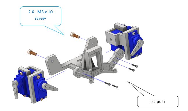
Fig. 17 Figure 3 – Assembling the femur and coxa linkage.
Warning
Ensure that the joint axes remain parallel to avoid torsional stress during motion.
Final Inspection
Once all joints are assembled:
Check that all servos can move without obstruction.
Manually rotate each joint to confirm mechanical freedom.
Tighten all screws gently but firmly.
Prepare for electrical testing and gait calibration.
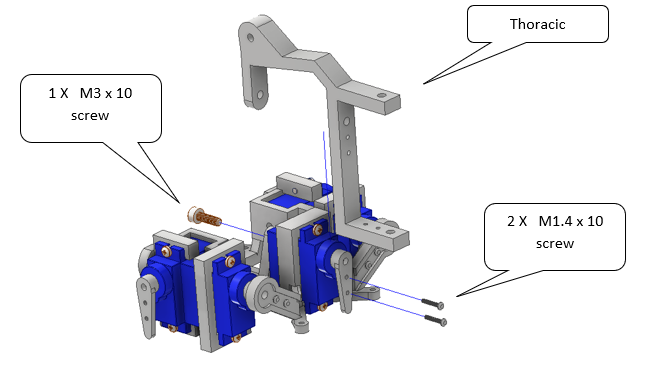
Fig. 18 Figure 4 – Completed leg assembly ready for calibration.
4.0 Attaching the Femur
Once the coxa is in place, attach the femur linkage.
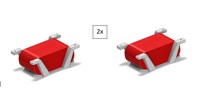
Fig. 19 Figure 5 – Completed leg assembly ready for calibration.
5.0 Attaching the Femur
Once the coxa is in place, attach the femur linkage.
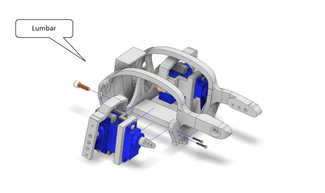
Fig. 20 Figure 5 – Completed leg assembly ready for calibration.
6.0 Attaching the Femur
Once the coxa is in place, attach the femur linkage.
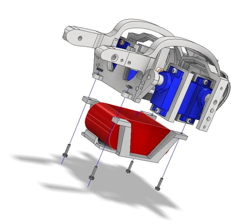
Fig. 21 Figure 5 – Completed leg assembly ready for calibration.
7.0 Attaching the Femur
Once the coxa is in place, attach the femur linkage.
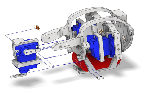
Fig. 22 Figure 5 – Completed leg assembly ready for calibration.
8.0 Attaching the Femur
Once the coxa is in place, attach the femur linkage.

Fig. 23 Figure 5 – Completed leg assembly ready for calibration.
9.0 Attaching the Femur
You have now completed the mechanical assembly of one leg module. Repeat the process for the remaining legs before proceeding to the electronics integration and motion testing sections.