Electronics Assembly
Overview
Now that the Evolutronix GUI and the state machine firmware have been successfully uploaded to the ESP32, we can proceed with connecting the electronics. This section covers how to power the servos, connect the PCA9685 servo driver, and safely verify the setup before motion testing.
Power Supply and Voltage Regulation
The servo motors require an external power source. We use a LiPo battery connected to a LM2596 voltage regulator to step down the voltage to a stable 6V output.
Connect the LiPo battery to the input terminals of the LM2596.
Using a multimeter, verify the output voltage on the LM2596 before connecting any components.
Adjust the output voltage: - Turn the potentiometer counter-clockwise to decrease voltage. - Turn clockwise to increase voltage.
When the output reads 6.0V, it is ready to power the PCA9685 servo controller.
Once confirmed, connect the LM2596 output to the V+ and GND terminals on the PCA9685 board. Make sure that the ESP32 continues to draw its power from the USB connection during setup.
Warning
⚠️ Critical Polarity Check: Always verify that the positive (V+) and negative (GND) wires are connected to the correct terminals. Reversed polarity will irreversibly damage the PCA9685 board.
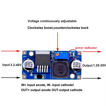
Fig. 11 Figure 1 – LM2596.
Connecting the evolutronix breadboard
With the power system ready, we can now connect and test the servos.
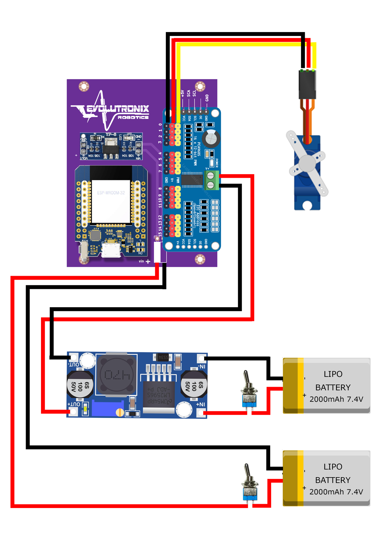
Fig. 12 Figure 2 – Wiring overview of the power distribution.
Connecting and Centering the Servos
With the power system ready, we can now connect and test the servos.
Connect a single servo to channel 0 on the PCA9685.
Ensure that: - The ESP32 is connected to your PC via USB. - The Evolutronix GUI is open and communicating with the ESP32.
Turn on the LiPo power supply. From the GUI, gently move the slider corresponding to the connected servo. You should see the servo horn respond smoothly to the movement command.
If the servo responds correctly, the communication between the ESP32, PCA9685, and GUI is confirmed.
Centering Procedure
Next, we need to center each servo before installing the servo horns.
Use the GUI to move each servo to its center position (typically 90°).
Power off the system temporarily.
Mount the servo horn so it aligns symmetrically with the robot’s neutral stance.
Repeat for all servos.
Note
Make sure to keep track of which servo corresponds to which joint or limb. Consistent channel mapping will simplify later motion testing and debugging.

Fig. 13 Figure 2 – Centering servos using the Evolutronix GUI.
Testing the Sequence Loop
After all servos are centered and horns attached, we can verify motion sequences.
Open the Evolutronix GUI and set servo parameters as follows:
Servo 0: Position = 30°, Speed = 5
Servo 1: Position = 45°, Speed = 3
Save these positions as a sequence.
Move the servos to a different position (for example, 60°).
Save again as the next sequence step.
Once the sequence is defined, you can play it using:
<LOOP,1>
<START>
The ESP32 will now run the stored sequence, cycling through the programmed positions at the specified speeds.

Fig. 14 Figure 3 – Executing a stored motion sequence.
Shutdown Procedure
When testing is complete:
Power down the LiPo battery first.
Disconnect the servos from the PCA9685.
Note the channel assignments (e.g., servo 0 = front left leg joint 1).
Store your configuration for future calibration.
Tip
During initial calibration, avoid mechanical load or obstacles near the servos. This prevents unexpected overcurrent draw or gear stress during startup.
Summary
You have now:
Assembled the power supply and verified safe voltage output
Connected and tested servo communication via the Evolutronix GUI
Centered all servo horns
Executed and validated a basic motion sequence
The next chapter will describe the mechanical assembly and structural alignment of the robot frame.